There are 10 images on this page.
John`s words of wisdom.
READ THIS WHILE THE PICTURES ARE LOADING.
An exhaust system is often part of the engine that is overlooked and just added at the end in the space that is left. This is a mistake as the exhaust system is a very important part of the vehicle. The prime aims for the exhaust are to carry the gasses away from the engine into the atmosphere without making too much noise and to help the engine make as much power as possible. Most people also think that achieving this is a black art, but it is possible to build an exhaust system that silences to a low noise level yet still produce power close or similar to an open pipe. The basic requirements are for silencers that flow 2.2cfm for every BHP the engine produces, a 4 branch manifold and an expansion chamber at the end of the collector to replicate the open atmosphere. I will expand on all these aspects as I build my system.
As my engine will produce around 200bhp I require a silencer that will flow at least 440cfm but to keep noise down the silencer will also have to be as large as possible. Unfortunately most silencer manufactures in the UK do not quote flow figures and when I asked Jetex (who happen to do a very good range of silencers aimed at the home builder) at the recent Autosports show I got a very negative response. The representative basically said I do not need to know flow figures.
Fortunately though, through the work of David Vizard many people are realising that flow of silencers is important and American manufactures are quoting flow figures. Walker Dynomax silencers are recommended by Vizard and they quote air flow figures, so silencer choice is easy.
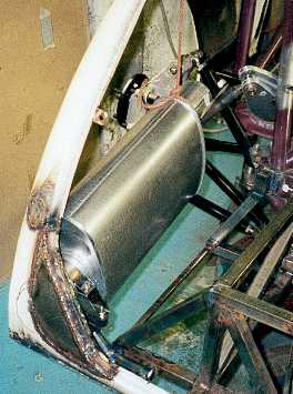
The silencer is huge
with a 5 1/2 x 11" oval body, 16" long. It has 3" pipes and
flows 525cfm, good for 239 bhp. It came from the USA and cost me £70.
It will sit in the back corner of the `boot' with the exit pipe coming out
of the rear body work. This has required a bit of new body work.
------------------------------------------------------------
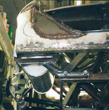
The silencer is mounted
on a substantial bracket insulated with small rubber mounts. The pipe will
run over the rear suspension and down the sill. This will mean that no part
of the exhaust will be below the floor level.
------------------------------------------------------------
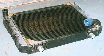
The radiator is a specially
made unit based on a narrowed 3.9 litre V8 Land Rover Discovery unit with
modified 90 degree bottom outlet. The mounts are on the top and bottom plates
and I had to solder reinforcing corner pieces in, to tie the end, tanks into
the plates. The radiator was made by a supposed top company (Serck) but was
not to the standards I wanted.
------------------------------------------------------------
The bottom mounts are
aluminium pegs bolted to the base of the radiator. These then drop into holes
in the front structure. I have wrapped ribbed rubber matting around the pegs
and will also have pieces on the base of the radiator. When making mounts
you have to consider the radiator full of water and the forces on the radiator
and mounts when driving hard, taking off landing etc.
-------------------------------------------------------------
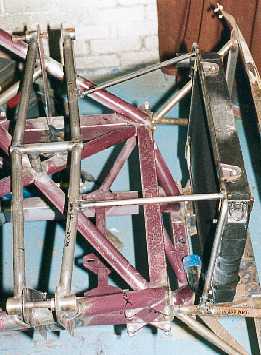
The top mounts are
again pegs but with Marina radiator mounting rubbers around them. The
tube frame work will also act as support for ducting. I intend to have
ducting on both sides of the radiator to guide the air into and out of
the car.
---------------------------------------------------------
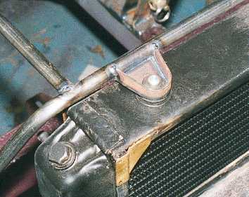
The top mount in detail.
It demonstrates the principal that thin material made into a structure is
lighter, stronger and more elegant than a single piece of thick material.
The tab joining the top plate and the end tank (the black one and not my new
brass one) was all that was holding the radiator together.
------------------------------------------------------------
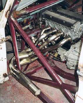
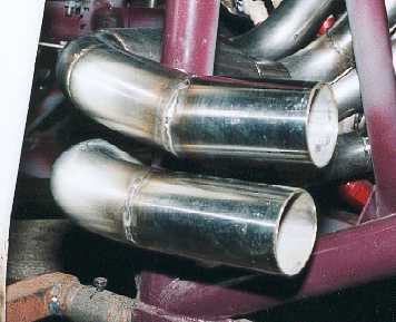
The exhaust manifold
in the car. Initially it looks very good but close up the standard of workmanship
is poor.
---------------------------------------------------------
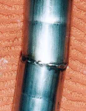
For example this picture
shows a join in the pipes which does not line up. This is one of many poor
joins. It looks poor and is very poor for flow due to the step in the pipe.
-----------------------------------------------------------
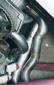
The pipes going into
the collector are not parrellel. The only reason the collector slips on is
that the pipes are such a sloppy fit. I am unsure how I was meant to get a
good seal.
-------------------------------------------------------
------------------------------------------------------
I am going to have to redo all of the manifold to get it to the standard I want. I took the car to the exhaust place so they could see the quality of work I expected. When I mentioned the quality of the manifold to them they did not think much was wrong with it. They had been recommended to me by 3 people, I have already had words with them!
I get so fed up of getting poor quality products. I try to deal with the best people to avoid these problems. I have even had problems with some parts supplied by a firm that does Formula 1 dampers!