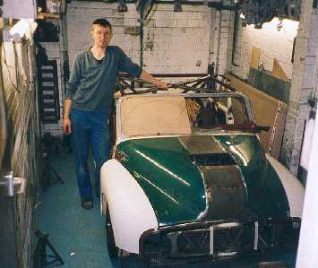
The builder stood by his Morris Minor at ride height. Check out how low the car is
and the small size of the garage. October 2002
I am currently working at least 4 days a week on the car and every evening. Progress is being made. The oil system is plumbed and the fuel system just requires the hoses making once I have some insulation to go on before I fit the ends. The fuel tank is ready to go together complete with 3 fuel pumps and an internal collector. This caused be some problems. I was going to use an internal collector from ATL. I spoke to them about it at the Autosports show and they said no problem, there website also says that there collectors are suitable for fitting into existing tanks. However ATL were not willing to supply the parts to me as they were not going into one of their tanks. I went to one of their main distributors and they agreed to supply me but the price was very high. So I built my own system and saved a lot of money.
I am now working on the wiring. There are 3 parts to the wiring. The Stack dash display has its own loom, supplied ready to fit. I am going to have a professionally made loom for my engine management as I want absolute reliability. And finally I will build a loom for the vehicle electric's (lights, horn, wipers etc).
I must be mad but I am already thinking of my next car. It will definitely be a kit car, able to take my mountain bike, be able to tow and be useable all year round as an every day road car. I reckon a kit car will be a piece of cake to put together after this and take very little time to build.

The reservoirs for the master cylinders are mounted around the diff.
This keeps the weight low and towards the rear. The brackets were awkward
to make though.

The Saab clutch release bearing plumbed. The top pipe goes to a bulkhead fitting
with a
bleed nipple.

The master cylinder plumbing. The reservoir pipes go down the chassis rail.
The RAC
blue book say "Not carry or pass any liquids in or through any tubes
comprising part of the
chassis structure or safety roll-over bar" I take this to mean in direct
contact and that hoses
down the chassis are OK. Besides its the safest way in my car.

The pipes exiting the rear of the chassis. All holes and openings are reinforced
to replace the strength lost by cutting the hole. The hole on the left is
for the fuel pipes.

Looking into the `engine bay`. It looks complex but it is really quite neat
and tidy. There is the oil tank, on the floor is the water oil heat exchanger
and at the front the steering rack.

Looking in from the side of the car.

This is a hole in the chassis (another one with fluids passing through) from
the
base of the oil tank to the pump. The sump is in the foreground.

The mounting for the oil filter is mounted on rubber buttons. This is because
the hose that goes to the engine is only 100mm long and I was worried about
the movement of the engine fracturing a fitting. Its surprising how big the
fittings are
and how short the hoses become. There is another hole in the chassis here.
They
were a pain to cut. I chained drilled then use the die grinder to open out
the hole.

The fuel tank top plate with outlet. The bulkhead fitting has to be above
the
the top of the plate (reason next picture), so I had to make a little adapter.

This is the internal collector, made of stainless (I can not
weld aluminium)
The high pressure pump is on the left and the braided hose connects to
the bulkhead fitting in the previous picture. Due to the hose being short
it
has to be straight, and is too high for a normal bulkhead fitting in the top
plate. The convoluted hose is a feed from a low pressure pump. I
discovered that only Teflon hose is suitable for in tank use.

This is a close up of the bulkhead adapter looking from below. It is basically
a top hat.
The bulkhead fitting is held in with Loctite 638 high strength retainer.
This is very strong and resistant to petrol.

The nut ring (left with top plate (right).

This is the internal collector with high pressure fuel pump.

The vent valve with internal ball bearing to prevent fuel
leakage if inverted.

One of the low pressure pumps. These are mounted in two corners
of the tank.
It took a lot of thought how to mount everything in the tank and get everything
in the tank with foam.

The return pipe also required a bulkhead adapter to reduce
the height of the fitting.
Again the fitting is Loctited into the adapter.

The adapter assembled with nut ring.

I have had to modify the seat mounts. I originally intend
to get at the fixings from
above but space is so tight down the sides of each seat this is not possible.
So I have welded in a tube and a bolt will come up from below into a captive
nut on the mount bolted to the seat. This does mean to take the seats out
I
will have to get under the car.

This is the panel by the pedal box next to the engine. It is 6mm thick! but
if the engine blows I do not want bits in my leg.