There are 10 images on this page.
The internet is a very good place to find out information. Many manufacturers and suppliers have their catalogues on line and this enables you to see what is available. Websites are a reasonable source but often the pictures do not show enough detail but if you e-mail the owners they will probably be willing to answer your questions. I have answered many questions and established contact with people around the world and they have provided me with valuable information.
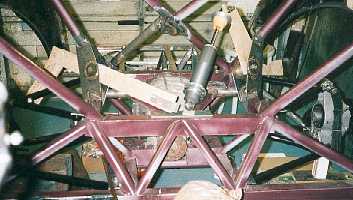
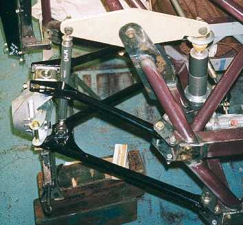
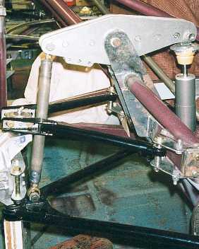
This photo is looking
rearwards and shows how the rear coil overs are mounted at an angle towards
the centre of the chassis. I am designing the coilover mounts on the chassis.
-----------------------------------------------------------
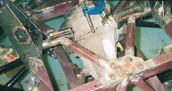
Where the mounts
go I have put a spreader plate. This is plug welded to the chassis rails
and will be welded along the edges as well
---------------------------------------------------------
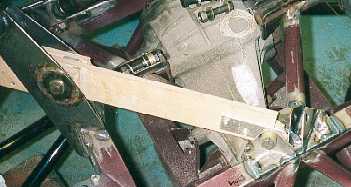
The piece of wood
is a jig that ensures the pushrod, pivot mount and coilover mount are
all in line. This ensures that there are no side ways loads on the rocker.
-----------------------------------------------------------
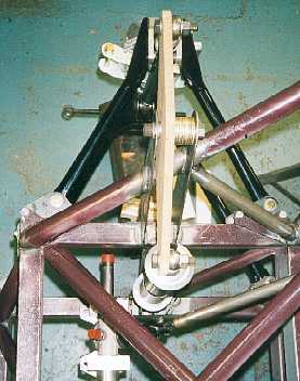
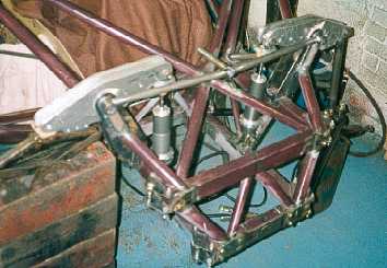
The mounting for
the front rocker and coil over are much simpler. Note how the steering
and coilover fit in nicely. The rocker is mocked up in MDF.
------------------------------------------------------------
The front rocker
is a simple design and the pushrod is nearly vertical. The inner side
of the rocker is longer than the outboard side to get a 1:1 motion ratio.
-----------------------------------------------------------
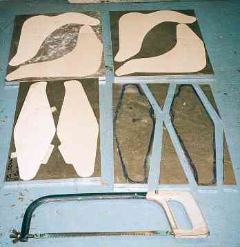
The rockers are made
from 7075 Aluminium alloy 1/2" sheet. I purchased four squares and
cut them out with a hacksaw. I used an angle grinder to dress the edges.
------------------------------------------------------------
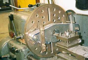
The rockers had a
hole bored in the centre to take a steel insert to house the roller bearings.
The fronts were bored on the face plate, but I had to mount the rears
on the vertical slide, on the cross slide and use a boring bar.
----------------------------------------------------------
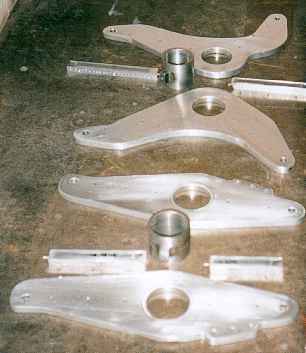
A front and rear
rocker before assembly. The steel tubes take the bearings and oil seals.
The rectangular pieces are the middle part of the " I " section
that will result when they are assembled. I used a high strength epoxy
adhesive to bond them all together.
------------------------------------------------------------
The front rocker
in position. The three holes in the rocker near the pushrod are for the
anti roll bar drop link. These holes are away from the main edge line
of the rocker so as no to act as stress raisers.
----------------------------------------------------------
This photo shows
how the front rockers and coil overs will be arranged. I am in the process
of making an upper cross member. This will also act as mounting for air
ducts from the radiator.
------------------------------------------------------------