There are 10 images on this page
John`s words of wisdom.
READ THIS WHILE THE PICTURES ARE LOADING.
Designing a steering system for a vehicle is quite a task with many factors
to consider, such as ackerman, rack position ( front or rear ), bump steer,
steering ratio and steering arm position on the upright. Millikens book Race
Car Vehicle Dynamics proved very useful as did Carroll Smith`s books. Again
I had to do a lot of research as my initial knowledge was low. Most of my
design decisions were dictated by the layout of the vehicle. A front rack
is used as this gives more room for the engine and smaller angles on the steering
column. Bump steer will be adjusted with spacers on the steering arms at the
upright. I will aim for zero toe change through the entire suspension travel.
One area which I always over engineer is the steering. It is one area that
must not fail in any circumstances. If your brakes fail at least you can choose
which tree you are going to hit, but if your steering fails, you can only
go where you go. Beware of welding on the steering column , I much prefer
mechanical joins and brazing.
Brake pad material can transform your brakes. Even if you have a standard
vehicle try some uprated pads. I always use Mintex M1144 for road use.
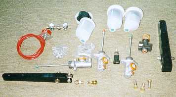
The brake components.
The pedals are fabricated from sheet steel and have sealed ball bearings for
the pivots. The master cylinders have 60 degree off set mounting flanges to
enable lower mounting. The reservoirs have rubber bellows in the caps to isolate
the liquid from the atmosphere but still allow the fluid to drop.
-----------------------------------------------------------
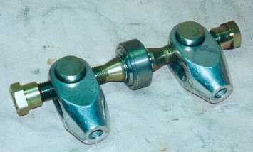
The brake balance bar.
This goes in the pedal and enables varying leverage to be applied to each
master cylinder. When one master cylinder operates the front brakes and the
other the rear,you can fine tune the brake balance by moving the pivot point.
This is often done remotely with a cable. This is a Tilton unit.
------------------------------------------------------------
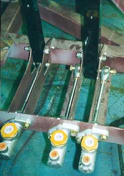
The pedal box with the
balance bar in position. The structure of the mountings will be improved when
a floor and foot plate are fitted. I have tried to make the brake pedal and
mounting very solid as the forces on them can be quite great when panic braking.
Notice how the pedal mounting plates extend to the master cylinders.
------------------------------------------------------------
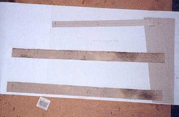
To determine the position
of the steering rack to eliminate bump steer I made a model of the suspension
so I could experiment with various track rod lengths and rack positions. Formula
exist which give the correct position and I used these but I wanted to try
them for real. There is a slot in the inner end of the track rod so I could
see whether the track rod altered in length when the suspension moved.
----------------------------------------------------------
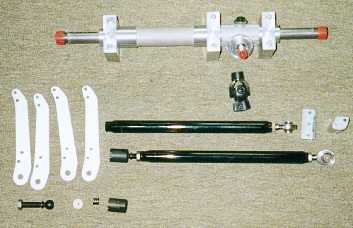
These are the components
for the steering. The rack is a Titan unit made to my specification. ( The
price is reasonable for a custom made rack, about a weeks wage when I purchased
it.) The 4 plates are the steering arms, by altering these I can change the
steering ratio and ackerman.
------------------------------------------------------------
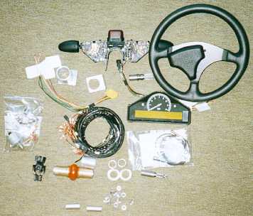
The steering column components.
The dash unit is self contained and will cover all my instrumentation needs.
It was expensive at a months wages but worth it. The steering wheel has a
quick release hub. This will help with entry and exit to the car and be a
theft deterrent.
------------------------------------------------------------
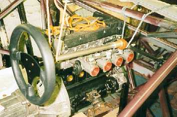
The advantage of a scratch
built vehicle is that I can position the controls exactly where I want them.
The steering wheel is positioned vertical in front of me.
------------------------------------------------------------
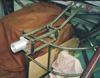
The column mounting combines
the bulkhead framework.The mountings allow the column to be dropped if required.
An air box will sit in the space behind the curved members.
------------------------------------------------------------
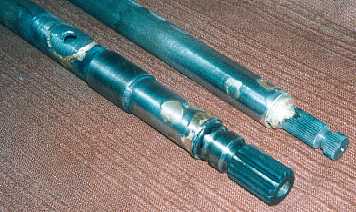
The ends of the column
which go into the steering rack uj and the quick release coupling. They are
pinned and brazed. The hole and reinforcing plate on the column in the upper
left of the picture is to allow wires to come out of the column.
---------------------------------------------------------
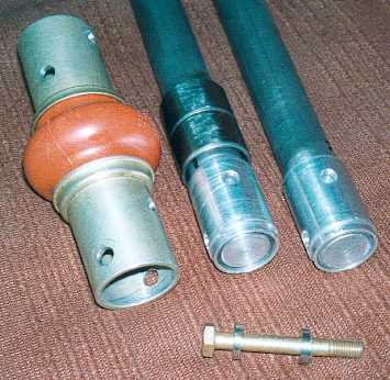
The middle uj and column
ends. The uj is a mil spec unit designed for helicopter control mechanisms.
It will bolt to the column. The column ends have aluminium bungs to prevent
crushing.
-----------------------------------------------------------