There are 10 images on this page.
The engine is a 2000cc Fiat twin cam from a 131 Fiat Mirafiori. The cylinder head is a 16 valve unit from a Lancia Integrale. Lubrication will be dry sump and induction will be fuel injection with throttle bodies controlled by electronics. To handle this torque and power a steel flywheel with an uprated Ford clutch will be required. These pages show the build of the engine by myself and reveal many techniques to help build a reliable torquey engine.
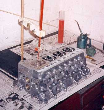
One of the problems of
fitting the 16V head to the 131 block is the pistons and getting the correct
compression ratio and piston cut outs. Here I am checking the volume of the
combustion chamber in the head.
------------------------------------------------------------
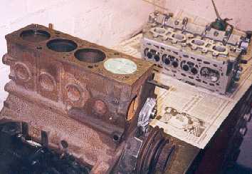
The advantage of the
Fiat engine is that the bores are common across a large range of engines.
This gives a wide choice of pistons with various cut outs, bowls and domes.
I used modelling clay in the bore to try out various piston shapes.
------------------------------------------------------------
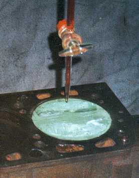
I buretted the modelling
clay pistons to get an idea of piston cut out volume and whether bowels or
domes would be required. Flat top pistons with cut outs will be required.
These can be obtained from a 131 OHC 1300cc engine.
------------------------------------------------------------
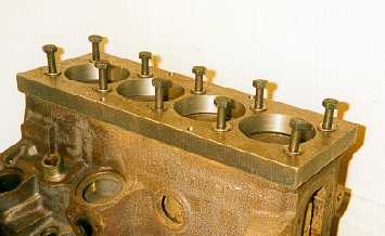
The block is bored and
honed with a piece of steel bolted to the block to replicate the stresses
induced when the head is torqued up. This will result in a perfectly round
bore giving better ring sealing, so less blow by and more power.
-------------------------------------------------------------
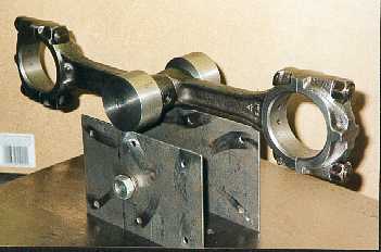
I balanced the con rods
myself using this home made fixture. It is accurate to within 2 gram. I proved
this by weighing 500 washers on some kitchen scales to find the weight of
one washer. I could then add a washer to one conrod and see it upset the balance.
It is important that the fixture is level. Pistons can also be balanced by
attaching them to the rods.
All sharp edges on the rods are radiused and new ARP bolts are used.
-------------------------------------------------------------
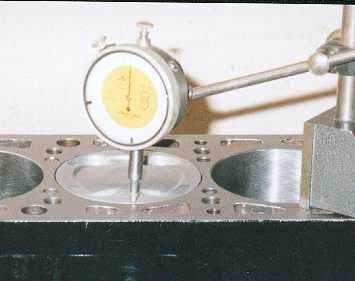
It is important that
each piston is comes equally flush or slightly proud of the block. This maximises
the squish and efficiency of the engine. I use the DTI to measure the difference.
By mixing the various rods and pistons in different bores it was possible
to get each one close. Final adjustment is made by machining the tops of the
pistons and then the block to suit. Note all the holes in the block are well
radiused. The piston has 4 cut outs and a small bowel.
------------------------------------------------------------
This is a crank scraper
designed to remove the oil from the crank and dump it into the sump. It is
made in 3 pieces from 2mm steel TIG welded together. A cardboard template
is made first then a lot of trial and fit work with the steel. A little is
filed off so crank clearance is around 2mm. There is about 8 hours work here.
I have a template of the scraper so I can make another if required.
-----------------------------------------------------------
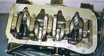
The crank scraper in
position. It sits between the block and the sump pan. I use Loctite 518 instant
gasket to seal the scraper to the block. The crank can hold a couple of pints
of oil as it spins ( like egg clinging to a whisk ), this causes drag and
is poor for oil control. The scraper removes oil on the cranks up stroke.
Front of the engine is on the right.
------------------------------------------------------------
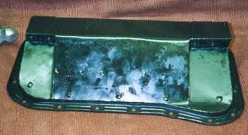
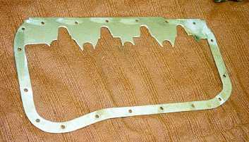
This is the dry sump
pan. The 2 cut outs at each end are for the outlet pipes. The basis for the
pan was a 131 sump but I only used the flange and 10mm of pan. The rest is
made from 1mm steel. Welding is by TIG and the pan was bolted to a block to
minimise distortion. The 5 lumps at the near lower edge are the heads of bolts
brazed in position. A lot of thought went into the design of the pan consideration
being given to how the oil will flow, the collection of the oil and the routing
of the pipes to the oil pump.
------------------------------------------------------------
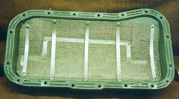
The inside of the pan
has 2 layers of stainless gauze. The top layer is quite coarse and is designed
to take the energy out of the oil after it has been flung off the crank by
the scraper. If the gauze was not there the oil would probably bounce of the
pan straight back onto the crank. The lower gauze is very fine as is intended
as a filter to stop any particles damaging the pump. The surface area is large
so it should not clog and can be easily cleaned by dropping the pan. Loctite
5900 flange sealant is used to seal the fine gauze. This sealant has good
high temperature oil resistance and can fill gaps up to 5mm.
-------------------------------------------------------------