There are 10 images on this page.
I have never built a four branch manifold before (only 2 into 1 for Fiat conversions in Minors) but after I was not happy with the one I had built I had no choice but to have a go. The important considerations for a 4 - 2 - 1 is that cylinders 4 and 1 join and 2 and 3 join, and that the pipes are approx. the same length. The secondaries should be approx the same length as the first pipes and be of a larger diameter. These then feed into a large single pipe.
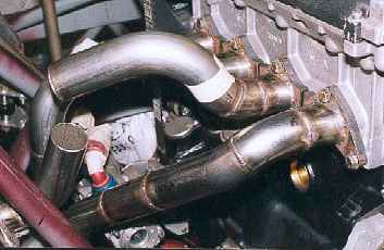
I started on the difficult to route pipes first and everything else nearly fell into place. The difficulty was getting the pipes approx. the same length.
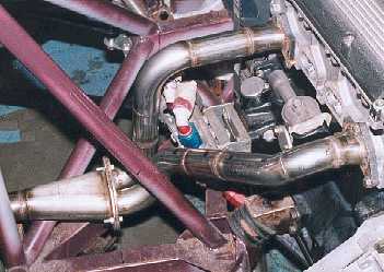
The first two pipes redone.
They are now much further away from the oil pump and fittings. I will be able
to get exhaust wrap on the pipes and some insulation sheet between the pipes
and pump. The only part of the original manifold that remains is the first
30mm of each pipe and the cone part of the collector.
------------------------------------------------------------
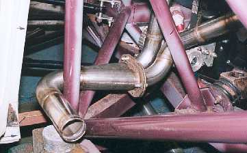
The pipe has to be a
close fit around the roll cage so it does not get too close to the door. All
joins on the pipe are now close fitting with no steps. The flange enables
me to remove the pipes easily.
------------------------------------------------------------

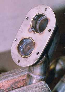
Once the first pipes
(cylinders 1 and 4 ) were done the next job was to position the collector
for pipes 2 and 3. The collector could then be connected to the appropriate
ports on the head.The flange is relieved to clear the door bar.
------------------------------------------------------------
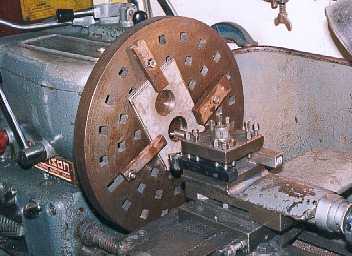
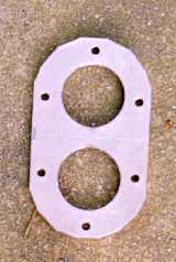
The flanges were made
from 5 mm stainless plate. I tacked the plates together then bored two holes
on the face plate of the lathe.
-------------------------------------------------------------
Even though I have quite
a bit of equipment often I have to resort to the basic hand tools. Here I
am hacksawing off the surplus metal. I am cutting 10mm of hard stainless steel.
It was hard work
---------------------------------------------------------
This is the result after
many cuts. It is now ready for the angle grinder to smooth the edges. After
the angle grinder I use a file for final finishing.
------------------------------------------------------------
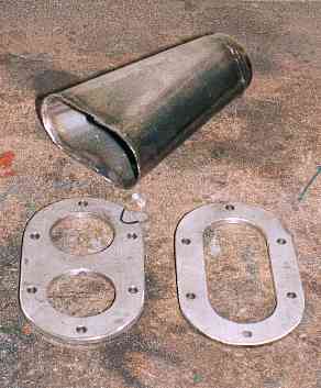
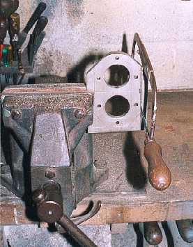
The parts of a collector
and flanges. The cone is salvaged from the original manifold with a short
flared section welded on the small end.
-------------------------------------------------------------
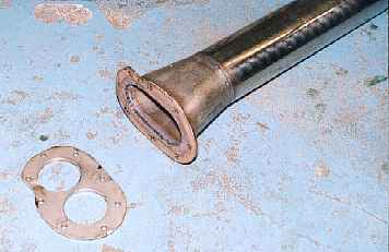
This is the final collector
and goes into 3" tube. The flange is relieved to clear the door bar.
Space is quite tight down the sill and I want the exhaust as far from the
door as possible.
------------------------------------------------------------
The pipes are put through
the flange and tacked on the outside. The surplus material is ground off this
side and the pipe seam welded.
-------------------------------------------------------------
When deciding the routing
of the pipes and which lengths of tube to use I found it useful to hold the
pipes with masking tape. The tape held the pipes firmly enough to mock things
up.
------------------------------------------------------------