There 9 images on this page.
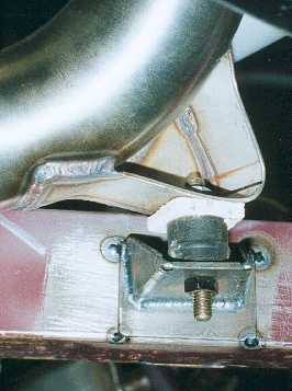
The middle exhaust mount
is on the lower bend of the rear pipe. I have tried to spread the mount over
a large area on the pipe so it will not crack.
------------------------------------------------------------
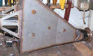
The expansion chamber
with reinforcing cross pieces. The large sides on the chamber could resonate
with the exhaust pulses and fracture the welds. I put pieces of 6mm rod across
the chamber.
------------------------------------------------------------
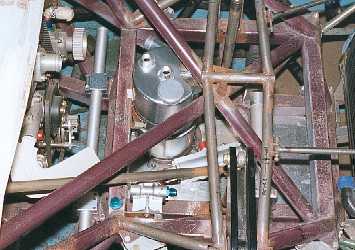
This is the space in
front of the engine. In this area I have the oil tank, oil filter, oil cooler
and anti roll bar. The anti roll bar is only mocked up in this shot and will
be a smaller diameter.
------------------------------------------------------------
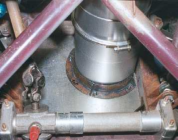
The oil tank sits on
the floor on a piece of rubber and is held in place by a curved bracket. As
the tank is sat on the floor the weight is kept as low as possible.
-------------------------------------------------------------
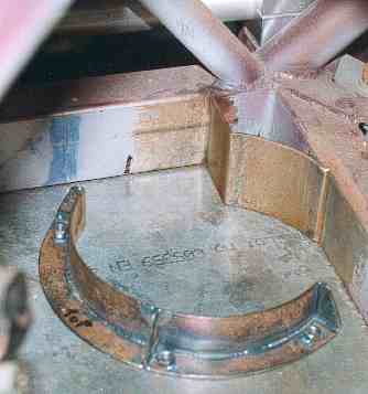
The oil tank sits up
to a curved plate on the chassis. There is another one further up the tank
to support the top. The curved bracket is bolted to the floor.
---------------------------------------------------------
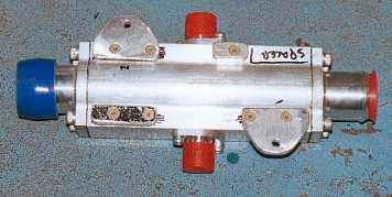
The oil cooler is a water
/ oil heat exchanger. This shows the underside with the brackets I bolted
on so the unit could be bolted to the floor. Again weight is kept as low as
possible.
------------------------------------------------------------
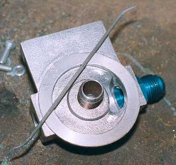
The oil filter is mounted
remotely on a housing. Just as you port a cylinder head for better flow I
port everything where there is flow. In this case oil flows, so radius all
the sharp corners to smooth the flow.
-------------------------------------------------------------
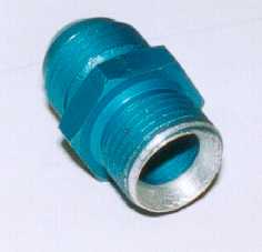
One of the fittings into
the filter housing presented a sharp protruding edge so I chamfered it for
better flow. The smoother the oil flow the less power required to pump the
oil. This is attention to detail that costs nothing.
------------------------------------------------------------
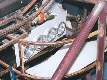
The picture shows the
mock up of an air box for the induction. The original plan was for an air
box bolted onto the injection units with a pipe down to an air filter in the
front grill. But I was worried about vibration with an air box so far from
the engine. I then realised that I had a ready made air box with the framework
on the chassis. So I required a flexible seal between the air trumpets and
chassis. Research on the Internet came up with bellows manufactures. I emailed
drawings for a quote and have ordered some bellows which will be made to my
spec.
-------------------------------------------------------------