There are 10 images on this page.
Building the manifold
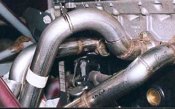
and getting the pipes to fit is like building the rollcage / chassis. This
pipe is close to fitting and now it is a matter of removing a little material
at a time until the pipe fits perfectly. It will be then tacked in position
and then removed and finally welded.
------------------------------------------------------------
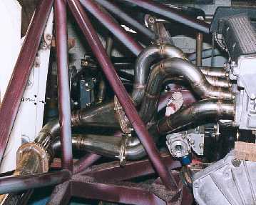
The finished manifold.
All the primary pipes are approx. the same length at 20", + or - 1",
the bends are smooth and the joins in the pipes close fitting. The manifold
will unbolt and remove without disturbing the rest of the system or the engine.
------------------------------------------------------------
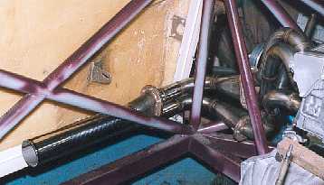
The exhaust runs down
the sill so no part of the system will below the floor. I am going to build
an exspansion chamber at the end of the pipe.
------------------------------------------------------------
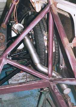
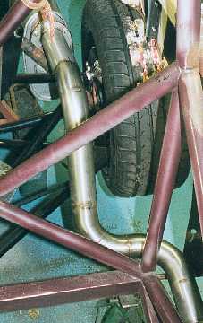
The firm (Tube Torque,
Macclesfield) built a rear pipe for me when I had the manifold made. Unfortunately
this is not correct either and will have to be redone. It runs too close to
the tyre and will not give me room to put an inner arch in. I am having to
buy two new bends to do this.
-------------------------------------------------------------
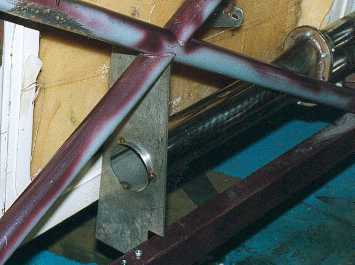
The rear pipe redone.
This gives much more clearance around the tyre. The pipe is 2 1/2" diameter
and this goes into the 3" pipe of the silencer offset to clear the suspension
pushrod. It could have gone in centrally but this would have meant that the
silencer would have been mounted higher.
---------------------------------------------------------
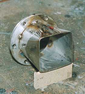
The output of the square
expansion chamber is round, so to get a smooth transition I had to make this
square to round adapter. It is made from a section of 3" tube with wedge
cut out to take it down to 2 1/2" (at the round end). A lot of hammering
and forming get it the correct shape.
------------------------------------------------------------
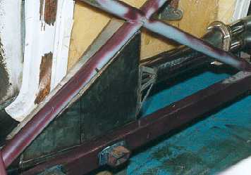
The expansion chamber
fits under the door bar and will be triangular in shape. To get the maximum
volume (important) I stepped it around the chassis rail. The excess 3"
pipe protruding through the plate will be removed.
-------------------------------------------------------------
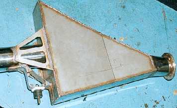
This is the finished
expansion chamber. The idea is that it replicates an open exhaust and the
sudden change in pipe diameter reflects a negative pulse up the exhaust. I
have tried to avoid any cracks by adding the gussets and plates.
------------------------------------------------------------
The expansion chamber
fits in well. I will add a lot of heat insulation to stop the door and seat
(when fitted) from burning.
-------------------------------------------------------------
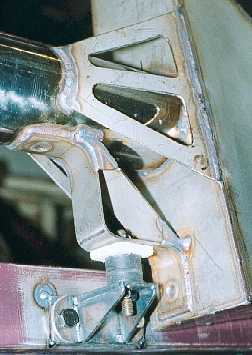
The front mount uses
a rubber mount with a block of insulation between it and the bracket. The
mounting on the expansion chamber also acts as a gusset..
------------------------------------------------------------