There are 9 images on this page.
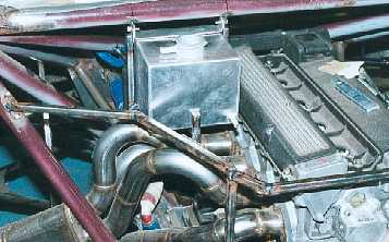
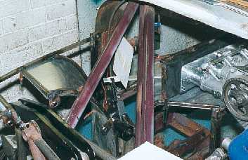
The header tank ideally
should be mounted high. This is one time where I have not been able to keep
weight low, but I have mounted it as far back as I could.
------------------------------------------------------------
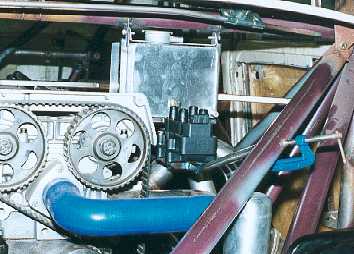
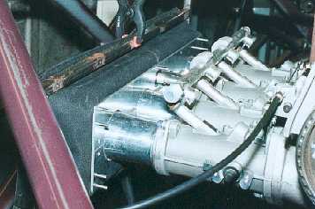
The coil block is quite
heavy and again should be mounted low, but it is important to keep it and
the plug leads away from any of the engine management sensors, so it had to
mounted next to the cyclinder head.
------------------------------------------------------------
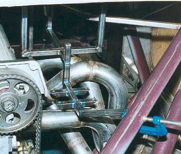
The mounting for the
coil and header tank is made from 1/2" box and bolted to the chassis.
------------------------------------------------------------
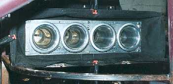
The flexible connection
between the air trumpets and air box. A split aluminium plate is attached
to the trumpets and throttle bodies.
-------------------------------------------------------------
The flexible bellows
allow movement between the engine and the air box which will be part of the
chassis.
---------------------------------------------------------
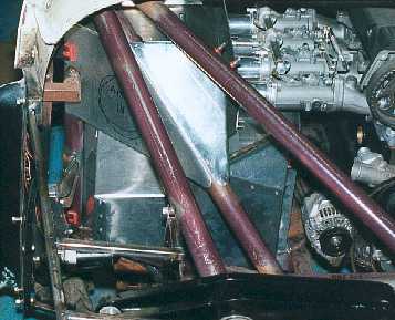
The piece of card is
the position where I want the inlet to the air box. This picture may help
to illustrate how difficult the panelling is when all I have is fresh air
to start with.
------------------------------------------------------------
With a bit of thought
I was able to make the air box.
-------------------------------------------------------------
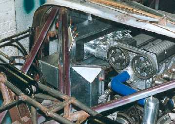
The flexible bellows
look very neat. The air box is big and should provide all the air the
engine requires.
------------------------------------------------------------
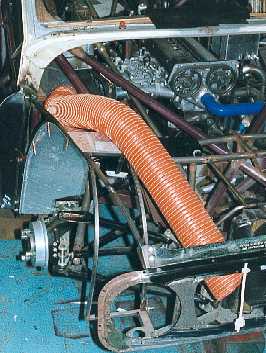
The 4 1/2" diameter
air pipe. I used the largest pipe that would easily fit. This area of this
pipe is nearly double that of the four throttle body chokes.
-------------------------------------------------------------