There are 10 images on this page.
The suspension for
this car is an area where I will spend a lot of time and effort. I always
like my cars to handle well and the suspension is an important factor
in achieving this. The suspension will be double wishbone all round. The
length of the wishbones will be as long as possible to reduce camber change
through the range of suspension travel. The wishbones will also have a
wide base to spread the loads in the chassis. I also intend to make the
wishbones symmetrical side to side to reduce spares requirements and ease
manufacture. All pivots will be by ball joints or spherical bearings.
I find spherical bearings perfectly adequate for road use if high quality
joints are used. The design will use spherical joints instead of rod ends
for cost and strength.
The first requirement for suspension design is tyre size. In my case this
is determined by what will fit in the Minor arches. A 15" diameter
tyre is about the maximum, this also allow more space in the wheel for
brakes. I decided upon a 195 45 15 tyre. Next I had to find some uprights.
The kit car industry offers a wide choice and a trip to a show enabled
me to find some. They use Ford parts so wheels will not be a problem.
I could now get some wheels, Ford Seirra Cosworth. All the components
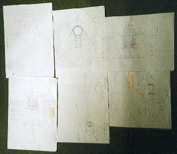
were drawn out and a computer program used to help me determine the pick
up points. First I decided what roll centres I wanted front and rear and
this gave me lines that the top wishbone pick up points must lie on. (
I am having the lower wishbone level. ) Then it was a matter of entering
points that lie on this line to give me low roll centre movement.
The actual design of the wishbones is intended to give good durability,
reducing stress raisers and be easy to manufacture.
I spent a lot of
time researching suspension set ups because I did not really have much
idea about different forms of double wishbone.
------------------------------------------------------------
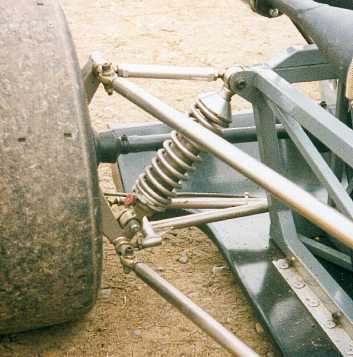
Most of the designs
I looked at told me how not to do things. Mountings in single shear, poor
load paths are all things I want to avoid.
-----------------------------------------------------------
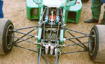

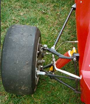
This was one of the
better designs that I saw. Symmetrical long wishbones which are simple
in design. Many magazines such as Race Tech and Race Car Engineering were
also studied for designs.
------------------------------------------------------------
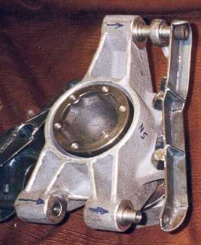
The front upright.
It takes Sierra bearings and hub. I have had to modify it quite extensively
to get my radial mount callipers to fit and to get steering arms on. It
has push fit taper bushes for the upper and lower balljoints.
------------------------------------------------------------
The rear upright
also accepts Ford bearings and hubs. It also required modification in
the form of extra brackets to ensure the mountings are in double shear.
-----------------------------------------------------------
Much measuring was
done on the uprights then drawings produced which enabled me to design
the wishbones.
-----------------------------------------------------------
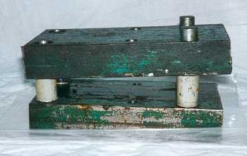
The wishbone tubing
is round CDS but to fit the spherical joints the ends of the tubes require
flattening to give more surface area to weld to. This jig is used in a
press to squash the tube the correct amount, at the correct angle. The
tubes were heated then pressed.
-------------------------------------------------------------
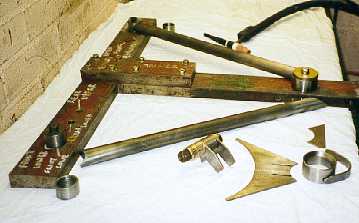
All the wishbones
are TIG welded on this substantial jig. Many hours of work went into designing
and making the jig to accept 4 different designs of wishbone. It does
however mean that all wishbones are dimensionally the same to within 1mm.
This is the front lower wishbone.
-----------------------------------------------------------
All bores on the
wishbones were machined to exact size after welding. The majority were
reamed using tapered reamers in a pillar drill. Getting them positioned
accurately so they cut straight and central was made easy with the taper
reamers as the part could be wedged onto the reamer and then clamped in
position. Getting the correct bore size was also tricky as feeds and speeds
of the reamer effected the size.
------------------------------------------------------------
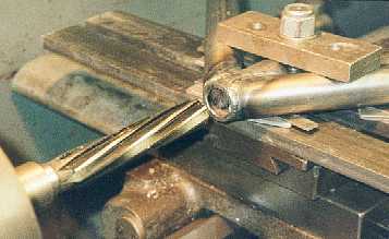
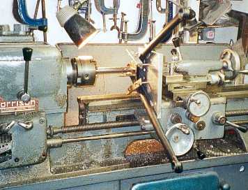
This is boring the
bottom ball joint housing on our lathe. Many fixtures were made and a
boring bar constructed . The machining went very well.
-------------------------------------------------------------