There are 10 images on this page.
John`s words of wisdom.
READ THIS WHILE THE PICTURES ARE LOADING.
I often find that one of the most difficult parts of starting a job is
having confidence that I am doing it correctly and getting going. Once
I am under way I realise that I was worrying too much. So have confidence
in yourself and attempt jobs. Also if somebody else can do a job then
I am sure I can, if I find out how they do it, I will be able to do it,
assuming that I have the correct equipment. Which brings in another subject.
We are fortunate to have a well equipped workshop but it hasn`t always
been that way. I built the Reliant with very basic tools but now with
more gear I do more work myself. For this new project I purchased a TIG
welder and small lathe, two essential pieces of kit. If you do not possess
a lot of equipment it just means you have to design your parts so you
can make them with what you have got. I often find it easy to design a
solution to a problem but much harder to design a solution that I can
actually make. If I had a mill and could use it then I would be able to
make nearly anything. Unfortunately we have not got the space for one.
So I have to subcontract any milling to DS ENG. (see links)
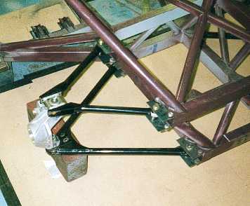
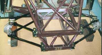
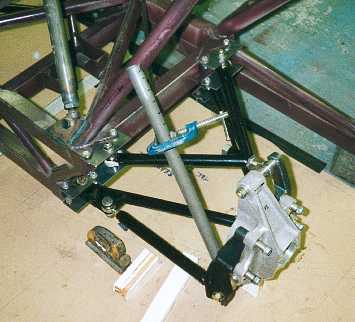
The front suspension
on. The plates to mount the suspension can be seen. The suspension pick
up points are within 2 mm and the geometry is within 0.1 degree.
-----------------------------------------------------------
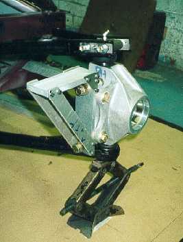
I had to make a castor
gauge as my inclinometer would not measure directly from the upright.
This took 6 hours to make. When measuring castor it is important that
the upright is pointing forward.
------------------------------------------------------------
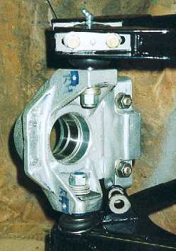
The steel push in
taper inserts for the ball joints in the upright could pull out so I have
doweled them in. Also a big washer sits on the alloy to ensure that they
definitely will not move. The manufacturer of the uprights says that an
insert has never come out but the fact that they could worried me.
-----------------------------------------------------------
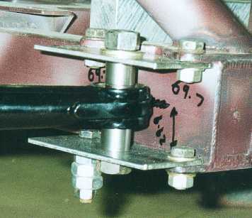
The mounting method
for the wishbones to the chassis offers me complete freedom in the position
of the pick ups. By making new plates and spacers I can alter the pick
up position. Also in a accident the plates should shear and leave the
chassis undamaged.
----------------------------------------------------------
This picture shows
the large size of the wishbones and how each pick up coincides with the
corners of the chassis. Pushrods will actuate inboard coil over units.
-----------------------------------------------------------
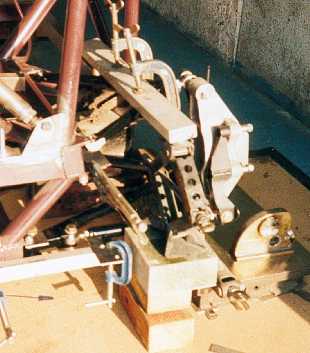
The rear suspension
was put together using the same methods as at the front. Castor was determined
by ensuring the bottom mounting bolts on the upright were level.( Using
the surface plate and scribe block.)
------------------------------------------------------------
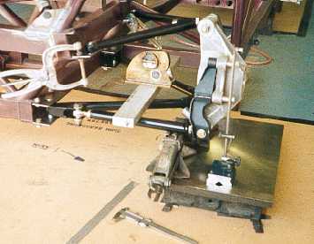
Clamps were used
to hold the plates while I measured the size of the spacers required.
Mounting the suspension took 6 days.
-----------------------------------------------------------
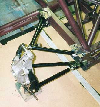
The rear suspension
in position. The steeper angled top wishbone is due to having a roll centre
that is higher at the rear.
------------------------------------------------------------
The rear coil overs
will also be in board operated by push rods. The positioning of the coilovers
will be angled to the centre of the car above the diff.
-----------------------------------------------------------
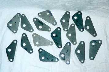
These are the plates
for mounting the wishbones. They will be plated to prevent corrosion.
----------------------------------------------------------