There are 10 images on this page.
The coilover units are going to be independently double adjustable single tube units. As these are relatively expensive (Typically £350 to £1000 per unit) they are going to be inboard mounted. This will protect them in the event of a crash and from road dirt thrown up by the wheels. But to achieve this I will have to operate them with pushrods and rockers. Another advantage is that I will be able to achieve a 1:1 wheel to damper motion ratio and the unsprung weight will be reduced slightly. As dampers rely on velocity of the piston to work this is important. Also a 1:1 motion ratio means lighter springs can be used. (Even though this is offset by the extra weight of the rockers and pivots.) Another consideration is that the mounts for the rockers and coilovers are inboard where the strength is in the chassis.
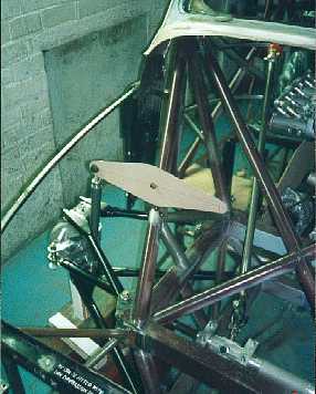
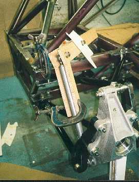
The front rocker
mounts on the front stay and is slightly longer on the coilover side to
create more movement to attain the 1:1 motion ratio.
-----------------------------------------------------------
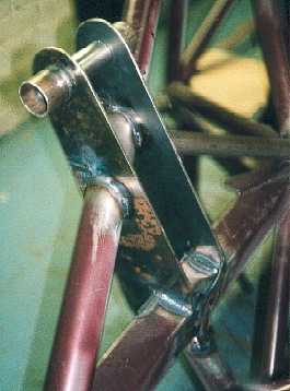
The front rocker
mounts are made from 3mm plate. The small tubes at the top are for the
mounting of a cross member.
------------------------------------------------------------
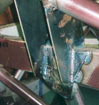
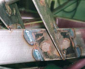
A spreader plate
was welded to the chassis rail before the rocker mounts were welded on.
The spreader was plug welded and laps down onto the upright tube. The
idea is to spread any forces over a large an area as possible and load
the welds in shear not tension.
-----------------------------------------------------------
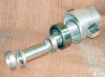
The rockers are going
to pivot on bearings. The choice of bearings was difficult as there are
so many types and then I had to estimate the forces involved to get a
size. I obtained a bearing catalogue and studied it. Eventually I chose
NJ type cylindrical roller bearings. They give the major load rating in
the radial direction with a small amount in the axial direction.
----------------------------------------------------------
The rear rockers
required quite a bit of thought as the coilovers are going to be mounted
at an angle above the differential pointing towards the centre. I was
worried that the pushrod would cause the rocker to bend.
-----------------------------------------------------------
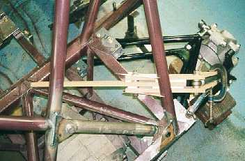
After experimenting
with thin hardboard rockers (relatively weak in bending) I discovered
that as long as all the points (pushrod, rocker and coilover mounting)
were in line everything worked. To ensure that everything is in line I
made a wooden jig.
------------------------------------------------------------
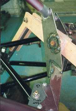
The rocker pivot
mount in position with the wooden jig for alignment.
----------------------------------------------------------
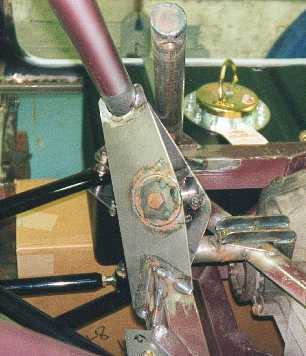
The circle of steel
around the fixing bolt is to spread the load. It is attached with plug
welding and the welds around the outside.
------------------------------------------------------------
This is a spreader
plate for the rear rocker pivot. It is plug welded to the chassis rail.
As the rocker mounting plates pull up I was worried about putting the
weld onto relatively thin chassis rail, hence the 3 mm plate to spread
the load.
----------------------------------------------------------
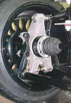
The rear suspension
upright. Notice how the lower wishbones are as close to the wheel rim
as possible. The wider apart they are the stiffer the installation, so
the less likelihood of rear toe change.
------------------------------------------------------------