There are 10 images on this page.
John`s words of wisdom.
READ THIS WHILE THE PICTURES ARE LOADING.
Car building is 90% mental. Its all about having the dedication to
keep at the task in hand and not to give in. Problems which initially
seem impossible to solve will become easier if you break the problem down
into smaller bits. Take time to do research and find out about the subject
you are tackling. Building a car is very time consuming, its nearly a
way of life. You have to be very selfish and concentrate on the project.
Sacrifices are made regarding money, relationships with friends and family.
Its not easy but that is the mental part I referred to. Actually shaping
materials is the easy part once you have decided what to do and how to
do it.
Here are a few more suspension tips.
Use the best tyres you can get.
Read Carroll Smiths To Win books and Nuts, Bolts, Fastener and Plumbing.
Race Car Vehicle Dynamics by Milliken is useful even if you do not understand
much of it.
Think what could go wrong and how things could break then design to avoid.
Use aircraft spec fastener on your suspension parts. They are not that expensive and you can get nearly any size you want.
I am not a trained
machinist so I have to think out every machining job. I made the boring
bar, with a high speed steel tool. This is held in by the grub screw and
there is another grub screw opposite the tool to advance it a little at
a time for each cut.
-----------------------------------------------------------
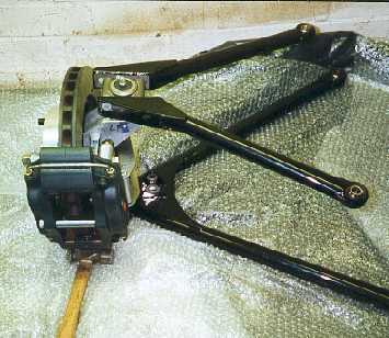
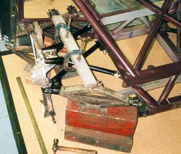
The front suspension
assembled with brakes. The top ball joint is Jaguar XJ6 and the lower
is modified Opel. The calliper is an alloy 4 piston AP Racing unit. The
disc is also AP Racing 280mm diameter and 25mm wide.
------------------------------------------------------------
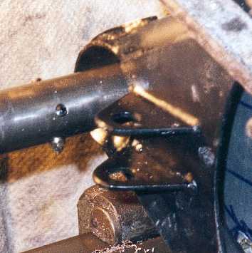
The top ball joint
created a few problems as I had to accommodate a square housing with round
tube. Also castor and camber adjustment is required. The dowel pin between
the 2 bolts will lock the camber in position.
-----------------------------------------------------------
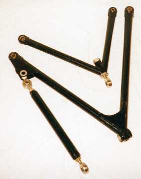
The rear wishbones.
The lower wishbones are on the outside and the upper is in the middle.
Castor and camber adjustment is done with the outer end of the upper wishbone.
Toe adjustment is done with the left hand link.
-------------------------------------------------------------
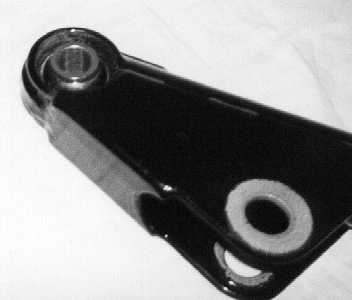

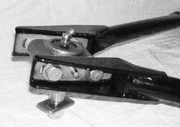
This is a close up
of the rear lower wishbone. The spherical bearing is held in position
with circlips and Loctite 638. There is a wrap around the housing so I
am not relying solely on a butt weld to hold the housing to the tube.
------------------------------------------------------------
The rear upper camber
adjuster. The camber is adjusted by turning the hex on the left. The use
of a rod end here is not ideal as I am worried about it bending by the
lock nut, but the upright layout dictated this design.
-----------------------------------------------------------
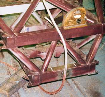
To fit the suspension
to the chassis I first required a level chassis. A water level is used
to level over distances. The inclinometer is used for shorter distances.
The inclinometer was picked up cheap from an auto jumble. It required
rebuilding but is very accurate. Note the suspension attachment points
on the chassis.
-------------------------------------------------------------
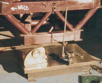
To ensure that the
pick up points are level on each side I used my surface plate, which was
levelled, to scribe marks on each side. I can then measure the distance
between the scribe marks and the mounting points and make spacers to suit.
-------------------------------------------------------------
Once I had established the position of one point the other is determined
by putting the wishbone level in all planes. Spacers are then made to
suit. The hard board on the floor is used for marking out the centre line
of the car and the pick up points. A plumb bob is used to check the actual
points match. This method does not require a dead level floor or true
chassis.
------------------------------------------------------------
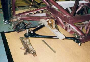
Once the lower wishbone
is in position the upper one can be positioned relative to it. The castor
and camber are set on the upright and the upper wishbone positioned so
the pick up points are correct referenced from the lower pick ups. The
actual positioning of the wishbone was quite awkward and took some time.
----------------------------------------------------------