Update 18th March 2004
If you wish to view previous work then links to updates are above. Work before this date was organised in sections (chassis, engine, bodywork etc.) you can see this work by going to "New Project Title Page" above.
The car is now very close to being ready for testing. All the body panels
are fitted (except the front bumper but I have made a temporary one), the
engine is mapped and I have fitted all the interior panels. The hood frame
is finished and the car goes for a hood making soon.
Over the last month I have been very busy often working long hours. Some
days I was in the garage at before 6am to do a bit before work and in the
evenings past 10pm was quite common.
Jobs left to do are limited. I need to get some testing miles to check
how everything is working. The suspension also requires a final set up.
I will also have top determine spring and damper rates.
I have been sending entries for hill climbs and sprints this summer.
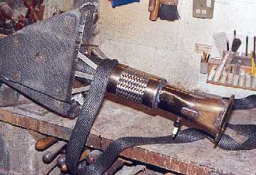
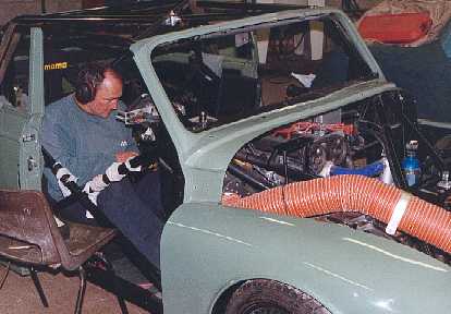
Due to the noise the exhaust system made I had to wrap it in insulation. This
will reduce noise and heat. I also put a flexy joint in before the expansion
chamber.

The expansion chamber was also covered in heat insulation
material. This was held on with stainless screws into threaded
inserts. Lockwire passes through the bolts and wraps the
chamber.
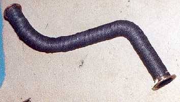
This is the rear pipe wrapped.

It was quite difficult to wrap the manifold due to the bends.
It was hard to estimate the length of wrap required and get it
to go around the bends. It is important to keep the wrap
as tight as possible.

I bought the wrap from an industrial supplier. It is the same as supplied
by motorsports
suppliers except for the price. A breathing mask is very important as lots
of fine fibres
are given off when handling.

This is a mount for the bumper.

The bumper mount screws into a captive thread on the chassis.
A stud is screwed into the outer end.

Here I am mocking up the front bumper. The towing point
passes through it and screws into the chassis.

These nuts are so good. They have an integral washer that is free to
spin. I have some with nylon inserts and some plain.
The big advantage is that as the washer is attached to the nut there is no
struggling to remove an washer from a stud and no chance
of loosing the washer.
The only problem is that I only have a couple of these. If anybody
knows of a supplier please let me know.

The glass fibre doors were very rough and took a lot of work to get
respectable. The main problem was voids under the gel coat
and dry CSM under the gel coat. They were also moulded off bent
and rusty doors.
This door is cut away to clear the exhaust.

To make the doors look better I put a layer of carbon on the inside.
I layed the carbon in then wetted it with resin (this allowed me to position
the carbon very accurately),
instead of the normal method of painting on resin first and laying the carbon
on top.
The doors look much better now and are stiffer.

The grill is stainless welded mesh. It is fixed to bolts bonded
onto the back of the panel. There are also studs to fix the panel
to the wings and chassis.

My Minor was originally fitted with trafficators, so I thought it
would be a nice touch to retain them. The trafficatiors are
available reconditioned but the brackets are very rare.
Fortunately I was able to borrow one and made some new ones in stainless.
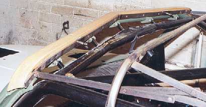
I had to make a new piece of metal that screwed to the wood
then attach the hood frame to it. The position was important
because the hood frame has to be tensioned when fitted.
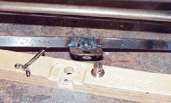
This shows the attachment details. The wing nut screw is the only
bought part.

Brother Robin and I spent 2 hours getting the frame to fit properly
We were concerned that each end overhung the window frame
correctly and the spars were in line.

As my front wings do not have the door pillar section I had
to put in a sealing strip.

This is the wire for the number plate light on the boot lid.
It is held to the carbon boot with hot melt glue from a
glue gun.

The boot lid is removable by pulling out the pip pin from
the hinges.

The windows are made from 5mm polycarbonate. This is very
impact resistant but soft. In the future I will make some more windows
and get then hard coated to prevent scratching.

This picture will only really mean something if you have tried to fit
convertible rear windows. The window rubber sits into a u shaped channel,
but as you fit the window it pushes into the channel and disappears.
I fitted a strip of closed cell foam (camping Mac) to prevent this.
The rubber was a nice snug fit with the foam and cured the problem.

The car went to a rolling road to have the engine mapped. After initial problems
connecting my ECU to the operators lap top everything went well.
The car behaved itself, there was no over heating and nothing fell off.

3 items were connected to the car. The "twiddle box" enables the
mixture
and ignition timing to be altered. The lap top runs the mapping software,
and the red
digital display is the lambda sensor to measure mixture.

This is a shot of the screen showing the fuel map being put
together.
The fueling is set at various rpm`s and throttle openings. I determined
the throttle points and had slightly more at lower throttle openings.
The operator Dennis mapping. He has mapped hundreds of engines
so hopefully he has done a good job.

This is the emmisions at tickover. 232 is the hydro carbons
which shows how much unburnt fuel is in the exhaust.
This is normally much higher with wild cams with lots of overlap.
I am unsure what the other figures mean. If anybody can comment on
them please let me know.

This shows flywheel figures and apparently the rollers read 10% low. The torque is very good 178 lb ft but it is shame about the big dip in the torque curve. The engine ticks over at under 1,00 rpm.


I may be biased but I think this looks very good.