There are 10 images on this page
The chassis for my
new project will be a space frame to connect all the major components
such as suspension, engine, coil overs etc together.
The main design considerations are torsional rigidity and to keep the
weight as low as possible ( in kg`s and height). The suspension pick up
points and the body shell are the prime constraints. I have to work inside
the body shell and the suspension design dictates exactly where the
suspension pick up points will go. Other definite parts of the chassis
are the main overhead loop, and the windscreen surround of the roll cage.
This also means I will have criss cross door bars, and roof brace. A wooden
chassis was used to play with the layout and to find good torsional
rigidity. Lengths of 6mm x 6mm wood was purchased from B&Q and this
was joined using a hot glue gun. Formica sheet was used to replicate
flat panels such as the floor ( again from B&Q ). The base of the
chassis will be 60 x 40 x 2 mm ERW (electric resistance welded) box section
again the suspension design dictates this. The upper will be 38 x 2.5
mm round CDS II ( cold drawn seamless, the II means hard as drawn and
not annealed ) as dictated by the RACMSA blue book regulations. The tubes
will be TIG welded together. This welding process is very neat but
is slow and awkward and the equipment is expensive.
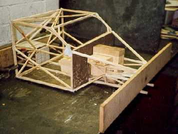
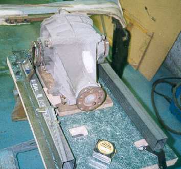
Initial designs of
the wooden chassis worked with a front
engine position and a flat bulk head. I made scale engine (with
induction), gearbox and differential so I could play with the
lay out. The main idea is to triangulate everything and support
every joint or bend as much as possible. By flexing the chassis
using the strips on each end I could see where the structure
was weak and try and reinforce it.
I tried hanging weights on the front strips and measuring the
deflection with a DTI ( dial test indicator, an accurate
measuring device) but could not get any repeatability so this
idea was not used. I had hoped to get quantitative values so I
could compare different chassis designs.
-------------------------------------------------------------
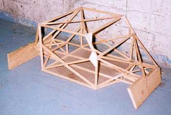
This shows the final
design of the chassis and was arrived at after
a lot of experimentation. The engine (not shown) is set a long way
back as this was the only way to get good torsional rigidity at the
front by putting diagonals across what would normally be the
engine bay. The small corner gussets in the windscreen opening
and the gusset at the base of the windscreen on the A post and
door bar junction increase the torsional rigidity significantly. I
discovered this by using the model and then saw similar gussets
on touring cars.
-----------------------------------------------------------------
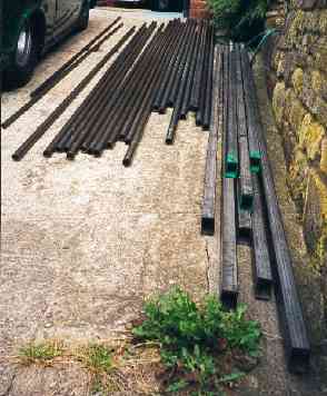
The lengths of steel
before storage in the workshop. I
purchased the steel from two local suppliers. ERW is easy to
get hold of but CDS is only stocked at a few places.The
round tube includes lengths of 1 1/4" x 16 SWG and
1 3/8" x 16 SWG for use as diagonals and reinforcement in
the frame. There is around £200 of steel here.
-------------------------------------------------------------
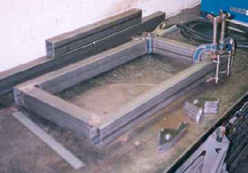
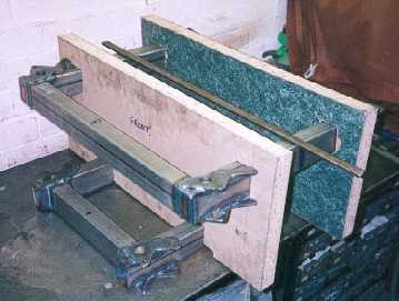
This is the start
of the front module which will hold the suspension
pick ups. It will be two squares of steel one above the other, the
lower for the bottom wishbones and the upper for the top
wishbones. In the foreground are the wishbone attachment plates
made from 5mm plate and the G cramps are clamping two in
position with alignment pins prior to welding.
-----------------------------------------------------------------
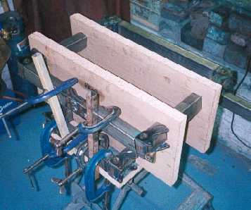
As the top wishbones
are angled down towards the centre of
the car the top members of the module have to be angled also.
The hardboard jig holds these at the correct angle and
position. The suspension attachment points can be seen and
the design of these means that the suspension pick up point is
adjustable by using shear plates and spacers. ( See the pages
on the suspension to observe how this idea works.)
------------------------------------------------------------
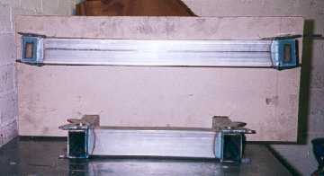
This end view shows
the slight angle ( 8 degrees ) of the top tubes.
The next job here is to link the top and bottom with round tube.
Then the jig can be cut out. I have actually started the cuts from
each corner of the square cut outs so I the saw will not have to go
right up to the steel.
----------------------------------------------------------------
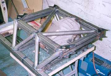
The rear module has
the added requirement of housing the
differential and ensuring that it can be removed without
sacrificing the stiffness of the structure. Therefore I had to
work around the diff. The design of the suspension again
dictates the position of the lower rails and there are also two
sizes of Ford diff. the 7" and the 7 1/2". I wish to be able
to
use both so I must design the mounts to take each housing
which fortunatly have similar attachment points.
------------------------------------------------------------
As at the front I
used a jig to align the top rails with the lower
ones. All the G cramps are holding the upper cross member in the
correct position. This upper cross member also has a cut out for
the upper diff. mounting. Again the suspension mounting plates can
be seen at each corner. I had to make 32 of these plates with
accurately drilled holes so I made a simple jig.
---------------------------------------------------------------
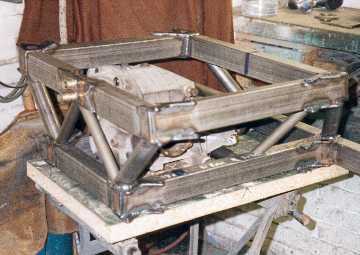
Tubes were shaped
to connect the top and bottom together
at the corners. The other tubes reinforce the diff. mounting
points. The nose ( front ) of the diff. has a mounting and the
forces on this are up and down ( an opposite reaction to the
rotation of the drive shafts ) hence the tubes from the top front
corners down to the lower rail.
-------------------------------------------------------------
The rear module completed.
The diagonals in the top triangulate
and also allow removal of the diff. The diagonals in the front
illustrate how to reinforce a open bay and how they combine with
the upper diagonals. You never feed forces into an unsupported
member.
-----------------------------------------------------------------