There are 10 images on this page
When profiling tubes
for the chassis there are several factors to get right. The ends have
to have the correct shape to fit the tube or tubes they
are butting up to, the tube has to be the correct length and the shaped
ends have to be orientated correctly to each other. The method below
demonstrates a technique to aid the shaping of multiple tubes. It involves
using a cardboard tube to duplicate the tube end profile to another tube.
Often a mirror image is required and this is obtained by turning the tube
inside out. Cardboard tubes can also be used to give an aproximate shape
for a complex profile.
Due to the symmetrical
nature of the chassis many of the tubes
are duplicated on each side but in mirror image. To speed up
the tube profiling process I make templates of the shape of
the tube ends, then transfer to the new tube.
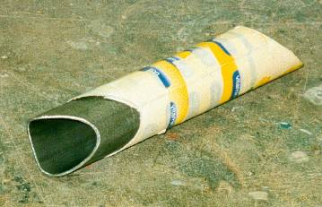
The first stage is to make a template of the first tube as shown
above. The cardboard is wrapped tightly around the tube and
taped. It is then cut to match the tube profile. Here it has been
slid down the tube .
--------------------------------------------------------------
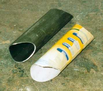
This picture shows
the template removed from the tube. Note
that both ends have been copied onto the template. This
means that the new tube will be the correct length with the
ends in the correct orientation to each other. On longer tubes
each end is done separately and the orientation done using
judgment.
--------------------------------------------------------------
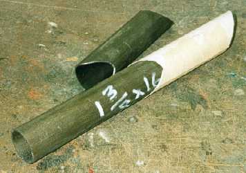
The template is then
turned inside out by removing the tape
reversing and taping onto the new tube, again tape it on
tightly.
--------------------------------------------------------------
The new tube is then
shaped to match the template. I do the
final fitting by trying the tube on the chassis. This ensures a
perfect fit.
--------------------------------------------------------------
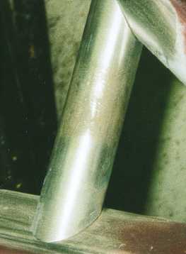

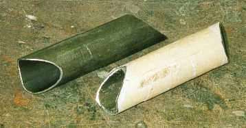
This picture shows
the fit between tubes which I try to get.
This ensures a better weld.
-------------------------------------------------------------
Welding the chassis
was a long task. It is important that I
spread the welding around to minimize heat build up and thus
distortion. It is also vital to be positioned correctly to get a
neat weld. This means the hands have to be resting on
something solid at around the wrist. To achieve this meant
using blocks and G cramps.
-------------------------------------------------------------


The chassis was put
on its side for a lot of the welding
-------------------------------------------------------------
This is a view of
the underside and shows how the bottom
rails bend to go around the engine.
--------------------------------------------------------
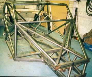
The basic chassis
frame completed. Now its just ( ! ) a matter
of attaching everything to it.
------------------------------------------------------------
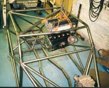
The next job was
to mount the engine. To get it into position it
has to go in through the roof. This necessitates a removable
member.
-----------------------------------------------------------