There are 10 images on this page
John`s words of wisdom.
READ THIS WHILE THE PICTURES ARE LOADING.
Even though building a car is a massive project with a lot of work
there will be times when you may well be stuck for something to do. This
can be avoided with careful planning. The secret is to have as many jobs
to do that can be done at any time and leaving them as emergency work
as long as possible. Concentrate your time and efforts only on the tasks
that are vital to the continuation of the project. These are the tasks
which are effectively preventing you from doing many other jobs. It is
also helpful if you can have several different avenues of work that you
can proceed down.
The main reason that you may run out of work to do is because you are
waiting for other people. This could be subcontract work or suppliers
of parts. The way to reduce this problem is to give them all as much time
as possible. For example the propshaft. The time to get a propshaft made
is as soon as the engine and gearbox and differential are mounted. Not
the day before the first outing. There is so much work to do after the
basic engine mounting it will give any propshaft shop plenty of time to
get the job done. Plan and think ahead, anticipate your work routine and
ensure you always have something to do.
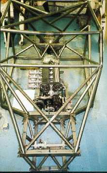
This picture shows
the engine in position with induction so I
can work out where the pedals and engine mounts can go.
------------------------------------------------------------
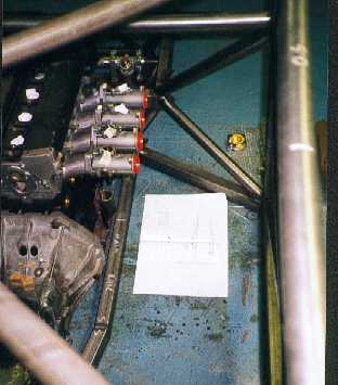
This is a close up
of the induction and pedal positions. I have
designed the pedals and their mountings and drawn them
actual size so I can move the paper around and try various
positions.
-----------------------------------------------------------
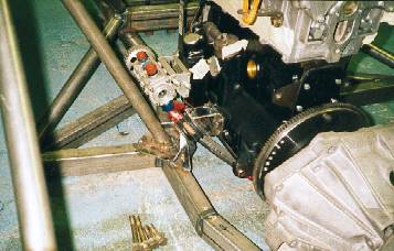
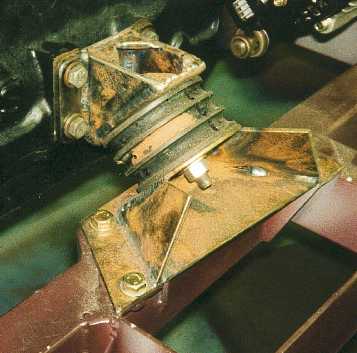
The off side engine
mounting. It may look like poor design
having all the engine forces going into an unsupported rail but
the pedal box will go in and strengthen things. Engine rubbers
are Jaguar XJ6, they are a simple donut design with a stud out
of each side and are very stiff.
-----------------------------------------------------------
The near side mount.
This mounting is very well supported by
the triangulated chassis member, but even so I have been very
carefull to feed the loads over a wide area as possible.
--------------------------------------------------------------
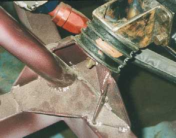
The drivers side
engine mount close up. A flat plate will be welded on the side nearest
so a vertical sheet of aluminium can be bolted to it. This will provide
leg protection from the engine and strengthen the mount.
------------------------------------------------------------
The passenger side
engine mounting close up. The mounting is gussetted in many planes to
spread the load over a wide area.
---------------------------------------------------------
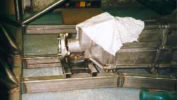
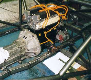
The gearbox cross
member is designed so that it will slide
backwards along the chassis rails. This means that to remove
the gearbox from the engine all I have to do is slide the
gearbox backwards once it has been unbolted from the
engine. This will avoid struggling with a heavy gearbox.
-----------------------------------------------------------
Most of the mounting
points in the chassis are captive, but to
do this I have to cut out squares and weld in steel with nuts
welded on the back. This was done by chain drilling, chisiling,
and grinding.
----------------------------------------------------------
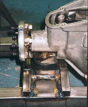
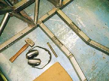
The finished gearbox
crossmember. The attachment points to
the gearbox casing have a tendency to strip so these are
Helicoiled and studs used instead of bolts. The rubber is again
Jaguar XJ6.
----------------------------------------------------------
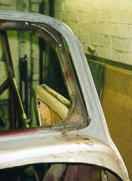
The wooden model
of the chassis revealed that the windscreen opening is a weak spot but
could be strengthened with gussets. These are the gussets as large as
possible without restricting vision. The bonded in screen will also help
stiffen this area slightly.
--------------------------------------------------------