There are 10 images on this page
Top Tips READ
THESE WHILE THE PICTURES ARE LOADING
Improve feed back through the base of the seat by removing all the
foam and sitting on a piece of camping matt.
Whenever something breaks ( anywhere not just on a car ) inspect the object
and determine why it broke where it did. This will help you recognise
weak points. Also determine the type of failure, fatigue, one time overload
etc.
Use the same suppliers and get known. Make their job as easy as possible,
give them as much information as they require. At Christmas take in some
beer. They do not have to give you discounts but often will if you ask.
Get to know about the different adhesives available and their different
characteristics. For example two part epoxies are often good for filling
gaps but have slower curing times. Super glues generally set very hard
and quickly and are suitable when you have a reasonable surface area.
The non setting paper adhesives on sticks have there uses. It is a matter
of using the correct adhesive for your application. Most manufactures
have technical help lines, use them.
I could now start
building the roll cage/chassis but to do this I
need some tubes bending. These are the overhead loop, the
members over the doors and the top windscreen member.
Tube bending is one of the few jobs which I get done due to
the equipment required to produce accurate bends. So that
the tube bender knows how to bend the tube I make
templates.
-------------------------------------------------------------
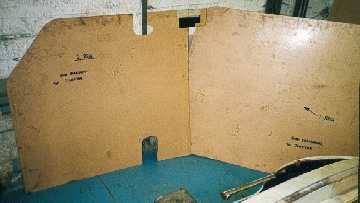
These are the finished
templates which I will supply to the tube benders. They are cut from hardboard
and their outer edge defines the required profile of the tube. I also
define the bend radius (this depends on the sizes of mandrels available)
and note down the tube specification. As I am using hard as drawn CDSII
it must be annealed before bending. The tube regains strength when being
bent due to work hardening.
-------------------------------------------------------------
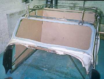
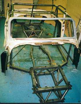
The tubes have been
bent and now it is time to position them
in the body so work on the chassis can begin. The main
overhead loop must be square to the centre line of the car and
body, plus be vertical on the uprights and level on the top. It
took me about one hour to be happy with the position.
-----------------------------------------------------------
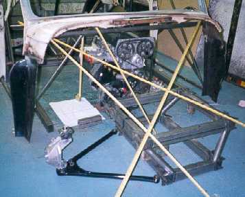
Even though I had
the design layout of the chassis I was not
sure of the exact position of all the members and engine. Here
I am using tapes to replicate tube position. I have to also
consider steering pedals and the angle at which the tubes join
other tubes.
------------------------------------------------------------
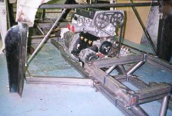
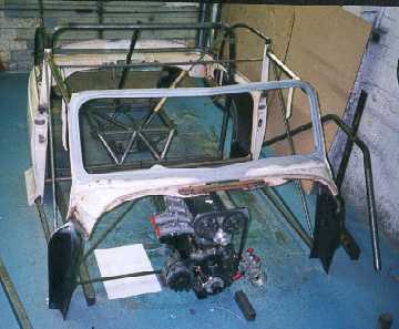
This picture shows
the engine with the front module and the
bottom chassis rails mocked up in position.
-------------------------------------------------------------
The bottom chassis
rails were all levelled using shims and a
straight edge due to not having a level floor.
-------------------------------------------------------------
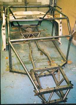
Once the basic outline
of the chassis/cage is defined in the
body, the body can be removed and work continue on the
chassis by adding tubes. The bottom chassis rails are tacked
before final welding. Most tacking is done with TIG unless I
have to hold a piece of tube then I use MIG.
--------------------------------------------------------------
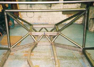
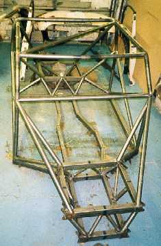
More tubes are added
and this picture shows nicely the
triangulation and how the suspension pick ups are supported.
I try to tack weld as much as possible before doing runs of
weld to minimise distortion, but this is not possible at a tube
junction as I have to weld the first tube before the second can
go on.
--------------------------------------------------------------

Work progresses adding
tubes. All the ends are shaped using
mainly large round and half round files, with some rough
shaping with a hacksaw and angle grinder. It takes on average
about 30 mins to do an end. Some of the front tubes were
especially difficult because I had to shape them to fit onto the
5mm plate of the suspension pick ups.
--------------------------------------------------------------
The front end in
detail showing the front module with steering
rack mount. The two front stays join the front module at quite
a low angle and only just fit on top of the square box section
without hanging over the edge. It will be very difficult to weld
the acute angle with TIG.
--------------------------------------------------------------